
Termination Resistor
It serves to reduce the effect of noise in the communication network, preventing failures and unnecessary disconnections, which allows for greater reliability of the data transmitted by the system.
The cables used in communication networks must have termination on their lines with an impedance value matching the characteristic impedance of the transmission line. If the load connected to the transmission line does not have the same impedance as the line's characteristic impedance, a portion of the signal travelling through the line will be reflected back toward the source instead of being fully transmitted to the load, causing signal loss and distortion. The impedance value of cable is associated with its geometry and the material used for insulation (this value is typically provided by the manufacturer). Twisted-pair cables have a characteristic impedance of approximately 120 ohms, making this the appropriate value for the termination resistor to be installed.
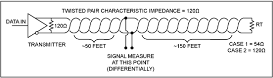 |
Figure 1 - Communication network. |
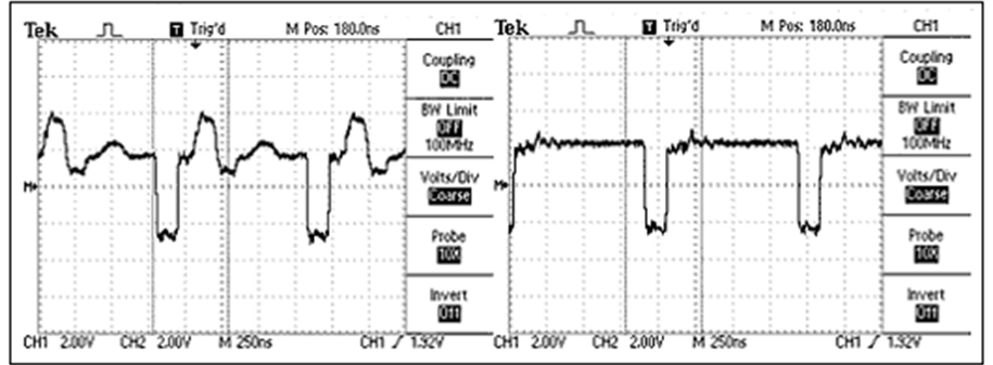 |
Figure 2 - Before and after installing the termination resistor in the communication network. |
Pull-up and pull-down resistors
The use of pull-up and pull-down resistors ensures that the logic levels high (1) and low (0) remain fixed while a digital input is not being used. In the absence of these resistors, the input may experience fluctuations. Fluctuations refer to unwanted variations in the logic levels of an unactuated digital input. These variations can be caused by external electric signals, high cable impedance, and electromagnetic interference from nearby devices.
Practical Example
To exemplify this effect, below ared images obtained from a test using an oscilloscope connected to an access point on a communication network with 5 Treetech devices interconnected in a daisy chain topology.

Warning!
The cables used for the test are twisted-pair in a controlled environment without equipment that generates major interference, therefore, noise control is already present. It is recommended that the user use shielded and twisted-pair cables throughout the communication network installation. For more information, access the following article:

Note !
If you have questions regarding the use of the oscilloscope within the communication network, access the following article:
Using an Oscilloscope for Communication Network Monitoring.
1. The first test was conducted without 120 Ω termination resistor and without 560 Ω pull-up and pull-down resistors. Note that there is a considerable noise in the displayed waveforms.
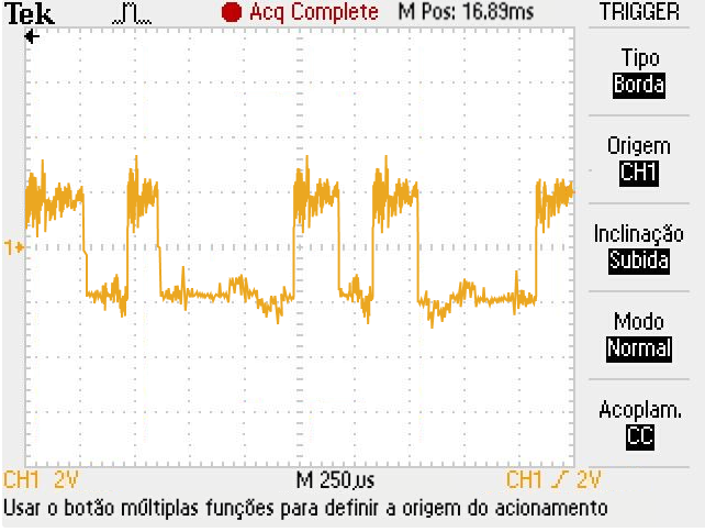 |
Figure 3 - Communication network without termination resistor and without pull-up and pull-down resistors. |
2. For the second test, termination resistors were placed at the ends of the communication network. Note that there was an attenuation of the network noise, but there is still interference in the waveform.
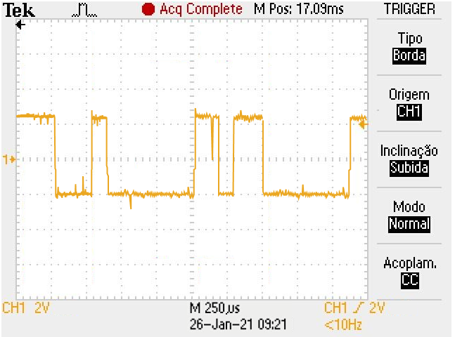 |
Figure 4 - Communication network with termination resistor and without pull-up and pull-down resistors. |
3. Finally, in the last test, pull-up and pull-down resistors were added in addition to termination resistors. It is possible to observe that there are no considerable interferences causing noise and distortions in the waveform.
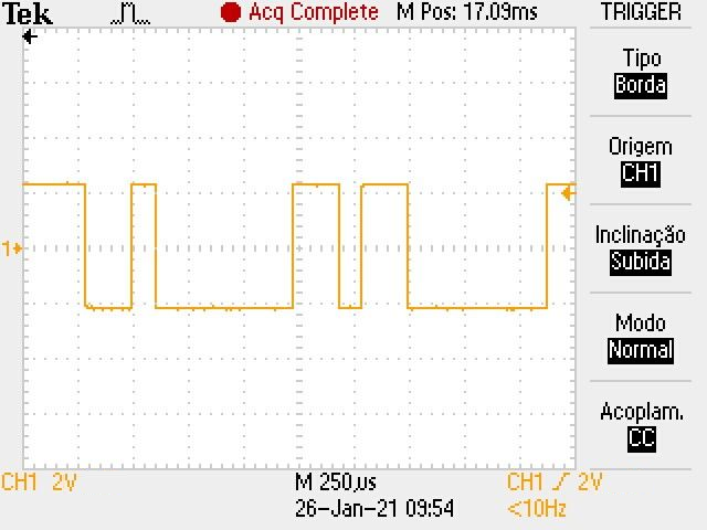 |
Figure 5 - Communication network with termination resistor and with pull-up and pull-down resistors. |
In all tests, communication was successfully established; However, in the first two, errors were present, along with slower communication between the IEDs. For this reason, as indicated above, we always recommend installing 120 Ω termination resistors and pull-up/pull-down resistors in the communication network.
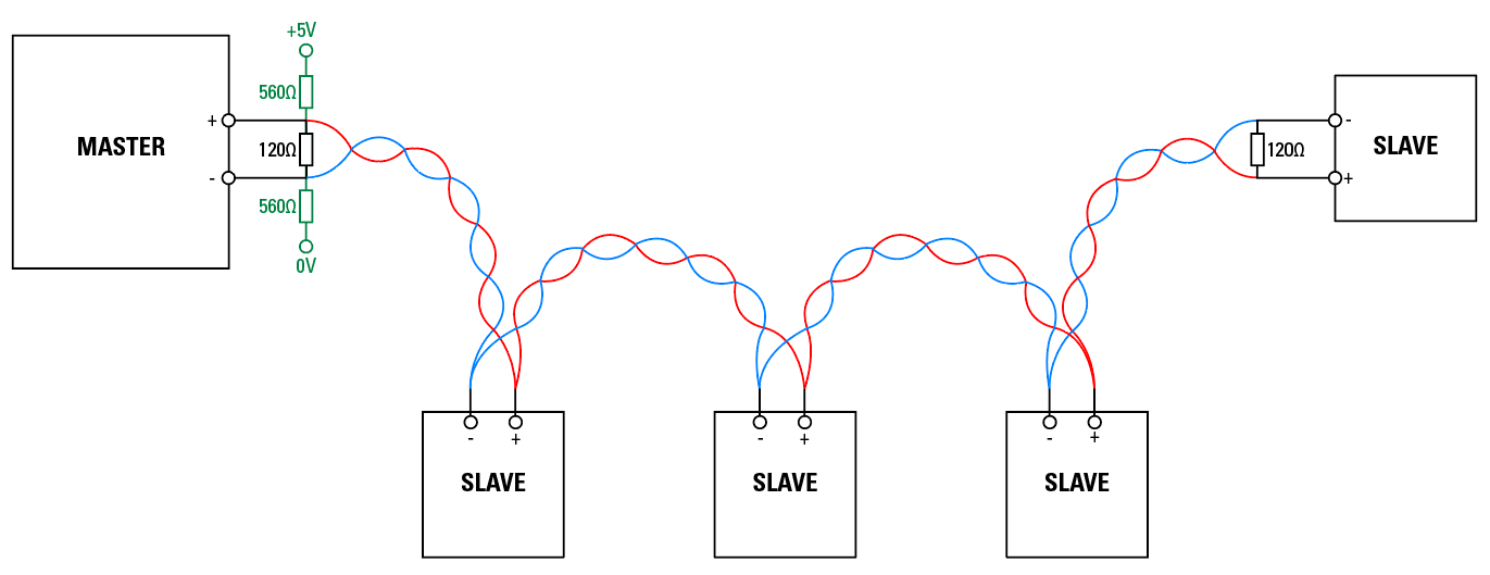 |
Figure 6 - Communication network topology using termination resistors and pull-up and pull-down resistors |

Information!
As mentioned earlier, it it highly recommended that the connection cables between the IEDs be twisted-pair and shielded. For more information about cable shielding access the following link:
Warning!
The source of the pull-up and pull-down resistor can vary between 3.3 and 5.0V; however, the value of the resistor should also match the source. As ideal for 120Ω lines, use the following configuration:
- 3.3V source with 330 Ω resistors;
- 5.0V source with 560 Ω resistors.
Was this article helpful?
That’s Great!
Thank you for your feedback
Sorry! We couldn't be helpful
Thank you for your feedback
Feedback sent
We appreciate your effort and will try to fix the article